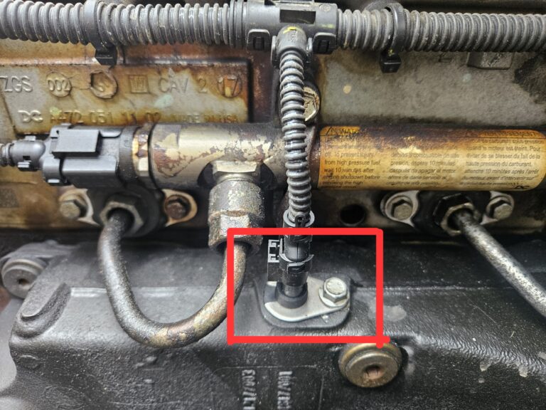
DTC P047F00
Exhaust Pressure Control Valve Stuck Open
Model: Volvo
Check Engine Light: On
Can Drive: Yes, reduced braking
Severity: High
Likely Cause: Stuck exhaust shutter or faulty pressure sensor
What Triggers This Fault Code
Heavy-duty diesel engines use an exhaust pressure control valve, sometimes called an exhaust shutter or exhaust back pressure valve, to help the engine brake and auxiliary braking systems generate resistance. DTC P047F00 sets when the control module detects that the valve appears stuck in the open position — meaning the exhaust back pressure sensor’s signal isn’t changing even though engine operating conditions are. In practical terms, the ECM expects to see pressure readings shift as load, RPM, or braking demand changes, but the signal stays flat.
This flat, unchanging signal is the defining symptom of the fault, and it usually points either to a stuck mechanical valve, a sensor that’s failed, or a wiring issue that’s preventing an accurate reading from reaching the control module.
Symptoms Drivers May Notice
Unlike some sensor codes that produce no drivable symptoms, this fault typically affects performance in ways the driver can feel:
- Reduced auxiliary brake performance — the auxiliary braking system won’t generate normal resistance.
- Weaker engine brake performance — engine braking feels noticeably less effective, especially on downgrades.
Because engine and auxiliary braking rely on exhaust back pressure to work properly, a stuck-open valve reduces the resistance these systems can create, directly impacting how well the vehicle slows down without using the service brakes.
Common Causes Behind the Code
Several components can be responsible for this fault, ranging from simple wiring problems to mechanical failures:
- Wiring harness — damaged connectors or damaged wires between the sensor and ECM.
- Exhaust back pressure sensor — damaged connector, internal sensor failure, or a damaged sealing ring.
- Clogged or blocked sensor pipe — restricts accurate pressure readings.
- Internal leakage at the sensor’s sealing ring.
- Exhaust shutter or air cylinder — physical damage preventing the valve from closing.
- ECM connector — damaged connector at the control module itself.
Step 1: Check the Sensor Connector (A14.EB)
The diagnostic process starts at the exhaust back pressure sensor’s electrical connector. With the vehicle fully powered off, disconnect the connector and inspect it closely:
- Confirm the connector is properly seated and locked.
- Inspect pins and terminals for oxidation or corrosion.
- Check that terminals are locked in place and not pushed back out of their sockets.
- Look for any physical damage that could cause a weak or intermittent connection.
Reconnect everything securely once the inspection is finished, then run a repair verification test to confirm whether the fault clears.
Step 2: Test the Wiring Harness
If the connector looks fine but a wiring fault is still suspected, the next step is testing the harness itself. This involves measuring voltage and ground at the component to determine whether the problem lies in the harness or elsewhere — such as the ECU output, battery, fuse, relay, or a ground point.
A healthy wiring harness should show close to zero resistance between connector ends. Technicians also confirm voltage supply and ground continuity at each relevant connector. As with any electrical testing, the power supply must be switched off before breaking any circuits or attaching test equipment.
Relevant reference points on the sensor connector (A14.EB) and sensor unit (B213) include the pressure signal pin, the 5-volt supply pin, and the ground pin — each of which should be checked against the wiring schematic for the specific circuit.
Step 3: Inspect the Exhaust Back Pressure Sensor (B213)
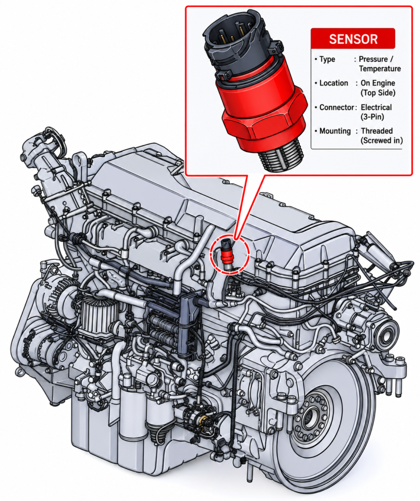
If wiring checks out, attention turns to the sensor itself. This involves a more thorough, multi-part inspection:
Connector check — Repeat the same connector inspection process used earlier: verify locking, check for corrosion, and confirm pin condition.
Visual inspection — Examine the sensor body and mounting for visible cracks, corrosion, or physical damage that could affect its readings.
Electrical test — Measure the sensor’s voltage output directly to confirm it responds correctly to changing pressure conditions, rather than relying solely on the ECM’s interpretation of the signal.
Leakage test — Check for internal leakage around the sensor’s sealing ring, which can allow pressure to bypass the sensor and produce inaccurate or flat readings.
Step 4: Inspect the Exhaust Shutter
If the sensor and wiring are confirmed to be working correctly, the fault likely lies with the exhaust shutter itself. Technicians inspect the shutter valve and its actuating air cylinder for physical damage, sticking, or debris that could prevent the valve from closing as commanded. A shutter that’s mechanically stuck open will produce exactly the kind of unchanging back-pressure signal this code describes.
Step 5: Check the Sensor Sealing Ring
The sealing ring on the exhaust back pressure sensor is checked separately for damage or wear. A compromised seal can allow internal leakage, which affects how accurately the sensor detects pressure changes, even if the sensor itself is otherwise functioning normally.
Step 6: Inspect the ECM Connector (A14)
Finally, if every other component checks out, the engine control module’s connector itself is inspected using the same connector-check procedure — verifying locking, checking for corrosion, and confirming pin integrity. A damaged ECM connector can prevent the module from receiving accurate signals even when the rest of the system is functioning properly.
Confirming the Repair
After completing fault tracing, all repairs that can reasonably be verified should be tested before returning the vehicle to service. Because some ECM diagnostic monitors require specific driving conditions that are difficult to replicate consistently, full repair verification may not always be possible within a single test. In these cases, completing thorough fault tracing and clearing the codes is the standard practice.
Final Takeaway
P047F00 points to an exhaust pressure control valve that isn’t responding to changing conditions, most often due to a stuck exhaust shutter, a faulty back pressure sensor, or a wiring/connector issue. Because this fault directly affects engine and auxiliary brake performance, working through the diagnostic steps in order — starting with connectors and wiring before moving to the sensor and shutter — helps pinpoint the actual cause efficiently and restore proper braking performance.