Engine Diagnostic Guide
SPN 1636 / FMI 2
Intake Manifold Temperature Reading Mismatch
| Can you keep driving? | Yes |
| Check engine light? | Yes, MIL comes on |
| Engine performance affected? | Possible Derate To 15 Miles |
| Common cause | Intake leak, sensor, or wiring |
This fault sets when the engine’s Motor Control Module notices a difference between the compressor inlet temperature and the intake manifold temperature that doesn’t match what it expects. In simple terms, air passing through the turbo and into the engine should heat up in a fairly predictable way, and this code appears when that pattern breaks down.
Monitored Parameter: Intake Manifold Temperature
The system keeps watch over the intake manifold temperature reading specifically. This isn’t checked constantly the monitor only runs while the engine is coasting between 500 and 1500 rpm, and it needs to stay in that range for at least five seconds before the check can complete. Once those conditions are met, the test runs continuously in the background.
Dash Lamps and Engine Reaction
If this code trips, the check engine light (MIL) will turn on. That said, there’s no engine reaction tied to this fault — meaning power, drivability, and fuel delivery all stay completely normal. But Sometimes engine can derate to 15 miles per hour. It’s a reading mismatch, not a performance issue , but in some cases it can cause.
Step-By-Step: How To Track This Down
Step 1: Check For Related Circuit Faults First
Turn the ignition to ON without starting the engine, and connect your diagnostic tool. Look through the stored codes to see if there are any circuit faults tied directly to the intake manifold temperature sensor. If there are, deal with those first, since they’re often the real root cause and can trigger this code as a side effect. If nothing shows up, move to the next step.
Step 2: Inspect The Air Intake System For Leaks
Turn the ignition off. This step means physically checking the entire charge air path — starting at the turbocharger connection, running along the intake tubing, all the way to the air filter housing, and including the seal where the housing meets the hood. You’re looking for any clamp that’s loose, missing, or damaged, and any seal that isn’t sitting flush.
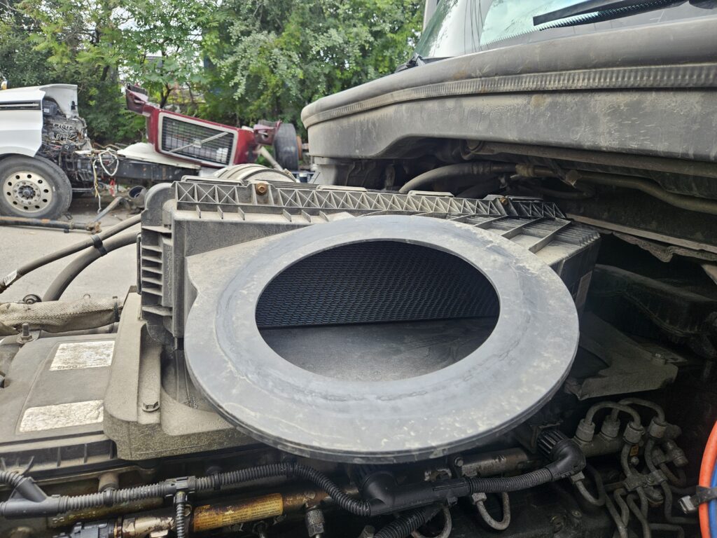
A leak anywhere along this path can let unmetered air into the system, which throws off the relationship between the compressor inlet and intake manifold readings. If you find and fix an issue here, take the truck for a road test afterward, making sure the engine hits the coasting conditions mentioned earlier so the system can confirm the fix.
Step 3: Inspect The Sensor Connector
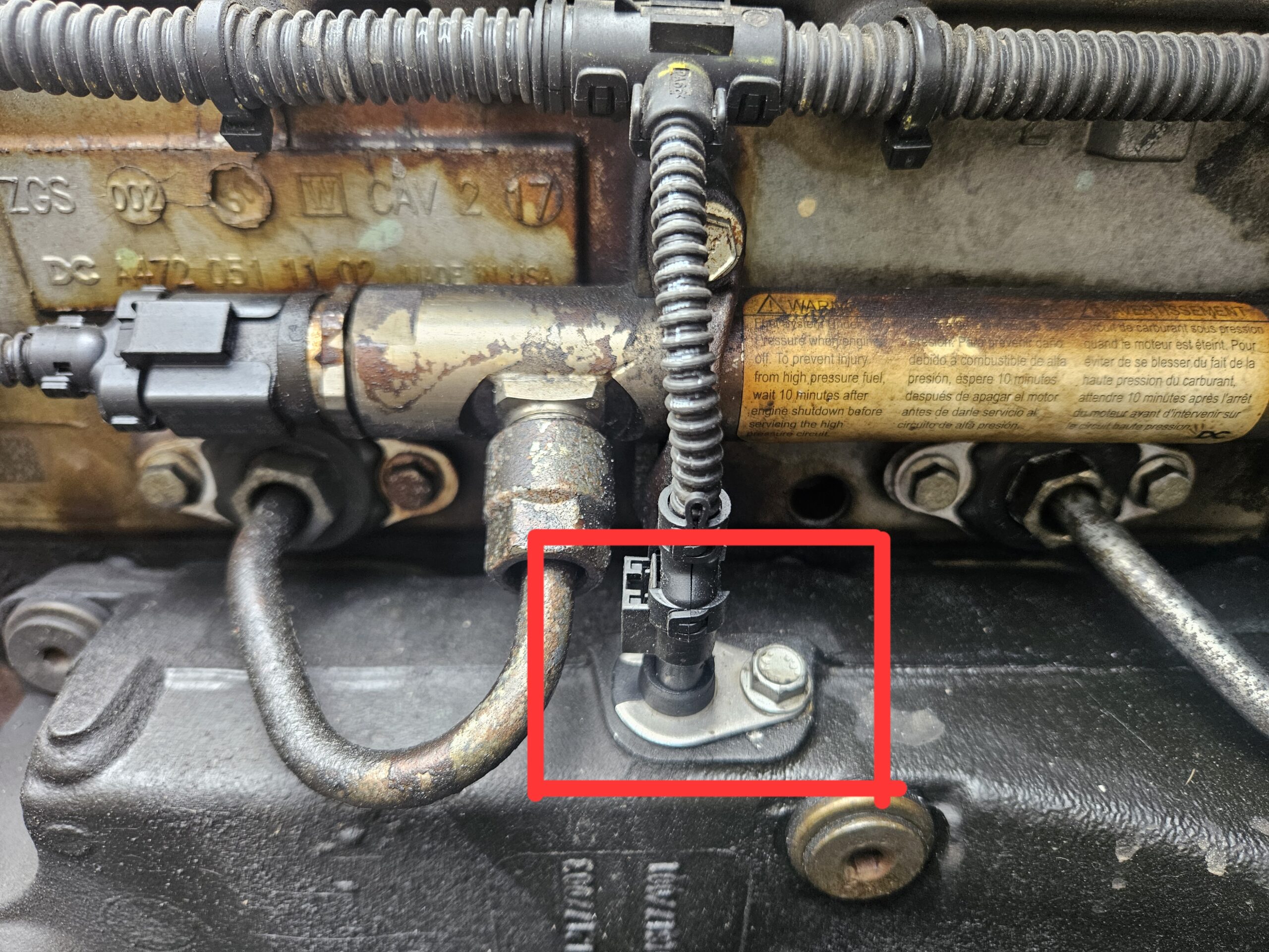
If the intake system looks clean, disconnect the intake manifold temperature sensor and take a close look at the harness connector pins.
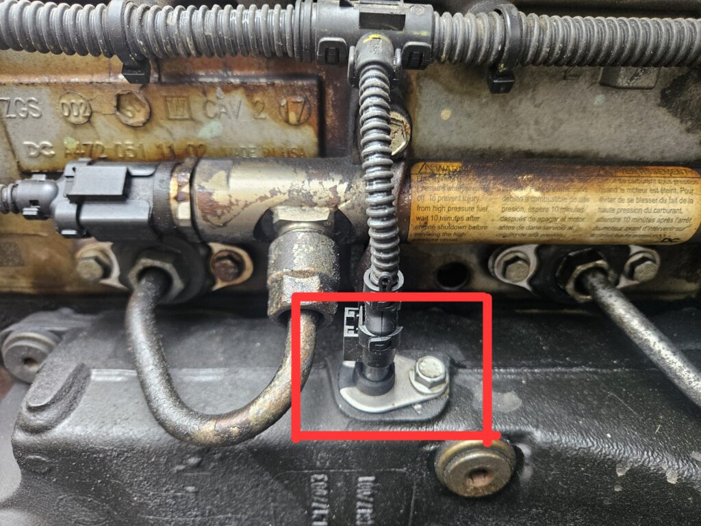
Sensor Location
You’re checking for pins that are bent, spread apart, or corroded. If you find any damage, repair or replace both the sensor and its pigtail harness, and that should resolve the fault. If the pins look clean and undamaged, move on to testing the electrical side of things.
Step 4: Test The Sensor’s Voltage Supply
Turn the ignition back to ON with the engine off. Using a multimeter, measure the voltage between pins 1 and 2 on the sensor’s harness connector. You’re looking for a reading between 2.75 and 3.0 volts.
- If the voltage falls within that 2.75 to 3.0 volt range, the sensor itself has likely failed and needs to be replaced.
- If the voltage reads below 2.75 volts, there’s a wiring issue to track down, which brings you to the final check.
Step 5: Narrow Down The Wiring Fault
With a low voltage reading confirmed, measure between pin 2 of the sensor connector and a good ground point.
- If that reading is also below 2.75 volts, the issue is in the wire running between pin 2 of the sensor connector and pin 106 of the Motor Control Module’s 120-pin connector. That wire needs to be repaired.
- If that reading instead comes back between 2.75 and 3.0 volts, the problem lies in the wire between pin 1 of the sensor connector and pin 52 of the MCM’s 120-pin connector, and that’s the wire that needs attention.
Confirming The Repair Worked
Once any repair is made, take the truck for a drive and get the engine into coasting conditions between 500 and 1500 rpm for at least five seconds. This lets the system’s monitor run under the exact conditions it needs, confirming whether the fix actually resolved the mismatch.
Good to know: This fault doesn’t cause any drivability issues, so there’s no rush — but a leaking intake seal left unresolved can gradually let in dirt and debris, so it’s worth fixing at the earliest convenient service.
Good To Know
Frequently Asked Questions
Is it safe to keep driving with this fault active?
Not always. In some cases, this fault can trigger an engine derate, meaning the truck loses power and may not be drivable normally. It can also push the system into asking for a regen, and the check engine light may flash red rather than staying solid.
What’s the most common cause of this fault?
A loose or damaged clamp or seal somewhere along the intake system is one of the most frequent causes, followed by a worn sensor or a wiring issue at the connector.
Why is the check engine light flashing red instead of staying on steady?
A flashing red light usually signals a more serious condition tied to derate or emissions performance, rather than a simple sensor mismatch. It’s a sign the truck wants attention sooner rather than later.
Why does the fault only get checked during coasting?
Coasting between 500 and 1500 rpm gives a stable, predictable airflow condition, which makes it easier for the system to compare the two temperature readings accurately without other variables interfering.
How do I know if I should replace the sensor or fix the wiring?
The voltage test is the deciding factor. A reading between 2.75 and 3.0 volts points to a failed sensor, while anything lower points to a wiring problem further up the circuit.